Log Periodic Antenna Design In Cst
This ability to share. The longest element is active at the antennas lowest usable frequency where it acts as a half wave dipole.

How To Simulate Wire Antennas Using Cst Microwave Studio Cst Mws Antennas Microwave Studio
The javascript starts with the minimum value of 076.
Log periodic antenna design in cst. The proposed antenna operates in the frequency range of 08 GHz to 25 GHz with satisfactory realized gain. Logarithmic Periodic Dipole Antenna Calculator. Show a good agreement with numerical simulation CST results providing validation of the design procedure and proof of the proposed antenna concept.
O A log-periodic antenna is a multi- element directional antenna designed to operate over a wide band of frequencies. As the frequency shifts upward the active region shifts forward. As we are dealing with an integer number of elements the.
The radio frequency interference is also needed to be known to prevent the original signal from getting disrupted. Identify the source of disruptive signals. LPDA or Log Periodic Antenna Design is another free antenna design software for Windows.
Contribute to dhanraj-mv8cst_log_periodic development by creating an account on GitHub. Detail of the endfed feed of a VHF logperiodic dipole array. The array elements are dipole antennas excited with 180o phase shift.
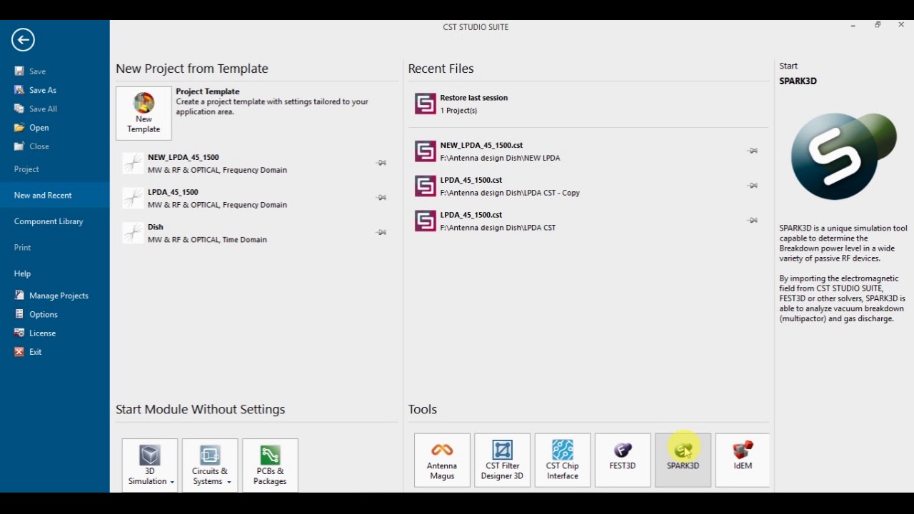
The log periodic antenna works the way one intuitively would expect. All these requirements are accomplished using log periodic antenna which we have designed for a frequency range of 350MHz to 1500MHz using CST. To design them you can use cylinders of PEC with inner and outer radius then make 2 triangles with extrude to cut them off.
Through this software you can design Log Periodic antennas. PESs Modern College of. Your text hereo Log Periodic Antenna was invented by Dwight Isbell and Raymond DuHamel at the University of Illinois in 1958.
1 along with the geometry-defining formulas. The antennas are designed for operation in the UHF-TV band ie. Optimal design of UHF TV band log-periodic antenna using invasive weed optimization P.
Introduction Today sharing information is easy fast and cheap. Their length and distance decreases according to 1 and 2 respectively where design constant called periodicity. Thank you very much for reading.
The basic arrangement of a log-periodic array excited by a two-wire line antenna feeder is shown in Fig. The simulated and measured S-parameter values of theproposed antenna are in good agreement and suggest a good matching of the antenna. A parametric analysis of proposed MLPDA antenna has been performed by using FDTD Finite Difference Time Domain based CST.
Your lumped port is not well defined or should i say its very wrong. The dipole elements are threaded on the outside. The feed coax is routed through the inside of the right boom.
Look at my port for the log-periodic. Gallion Abstract A powerful evolutionary method called Invasive Weed Optimization IWO is applied to achieve optimal designs of log-periodic antennas. Log-periodic dipole antenna Printed antennas Miniaturization techniques Standard antennas Antenna measurements Broadband antenna.
Read 8 answers by scientists to the question asked by Swetha Velicheti on Jan 4 2021. Only the center conductor of the coaxial cable is connected to the left boom by means of a rivet. Log Periodic Antenna Design.
The optimization algorithm used is TRF. Polymer standoff insulators between the parallel booms are also visible. I assume 50um is lambda4 for your lowest frequency i havent checked this.
It is very interesting to me due to the fact that im designing the same thing. These antennas are used in a variety of applications like UHF Terrestrial TV HF communications EMC measurements etc. Its active region that portion of the antenna structure which is actually radiating or receiving radiation efficiently shifts with frequency.
Why is your radiation boundary unequally distanced from the antenna in the z-axis it is -50um but in the xy-axis its more. Conclusion highly directional antennas with high gain. If a solution could be found is increased as long as the length of the boom is shorter than your design goal and as long as is smaller than the maximum value of 098.
The variable S1 is related to the angle at the center and it can be. The upper frequency limit of the antenna. Cost-effective optimized log-periodic antenna design is proposed to provide a solution to solve the significant problem of interference caused by LTE in TV broadcasting band to the receiver.
An optimized 12-dipole printed log-periodic dipole array antenna is proposed for L-band EMC applications. The proposed antenna design provides good antenna performance in the TV passband 470 MHz-790 MHz thereby rejecting LTE stopband 810 MHz-900 MHz. Hi Does anone have log periodic antenna simulation in CST or HFSS.
470-860 MHz and are. Relative spacing of. Variations of scale factor spacing constant and feed length analyzed for different values which significantly affects bandwidth and gain of proposed MLPDA.
This paper presents a Microstrip Log Periodic Dipole Array antenna design based on geometrical parameter variation for attainment of desired resonant frequency operating bandwidth and gain.

Pdf An Optimal Design Of Printed Log Periodic Antenna For L Band Emc Applications

How Can I Simulate A Horn Antenna In Cst Studio With The Widest Radiating Characteristics

How To Design Simulate Helical Or Helix Antenna Using Cst Studio Suite Design Antenna Studio

Antenna 300 1800 Mhz Youtube
Cst Optimized Model Of 10 Dipole Log Periodic Antenna With Lte Band Download Scientific Diagram

How To Design Simulate Yagi Antenna Using Cst Studio Suite Design Antenna Studio

Log Periodic Dipole Antenna Geometry Download Scientific Diagram

Cst Simulate A Free Space 2 Port Measurement Forum For Electronics

Yagi Uda Besic Design And Simulation With Folded Dipole Using Cst And Antenna Magus Youtube

Electromagnetic Simulation Solvers Cst Studio Suite
A Cst Model Of The Proposed Plpda Antenna Download Scientific Diagram
Cst Simulated S Parameters Of The First Folded Dipole In The 14 Pair Download Scientific Diagram

Antenna Simulation Tools And Designing Of Log Periodic Dipole Antenna With Cst Studio Pdf Free Download
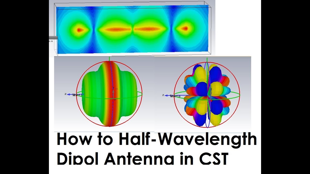
How To Simulate Half Wavelength Dipole Antenna In Cst Studio Suite Dipole Antenna Antenna Studio

Cst Tutorial 2 Design Of 5g Microstrip Patch Antenna In Cst Microwave Studio Youtube

Parametric Evaluation Of Microstrip Log Periodic Dipole Array Antenna Using Transmission Line Equivalent Circuit Sciencedirect

Geometry Of The Bow Tie Antenna With Hfss Cst Computation Parameters Download Scientific Diagram
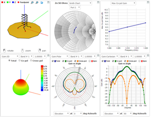
Lpda Design 45mhz To 1500 Mhz Using Cst Mws Youtube
Antenna Design Analysis And Simulation 2017 11 29 Microwave Journal
Post a Comment for "Log Periodic Antenna Design In Cst"